How to Read and Interpret Electrical Shop Drawings Part Two
3- Resources used to Read and Interpret Electrical Drawings. The electrical installations in any building can be represented on drawings by the use of the various applicable outlet and equipment symbols, together with interconnecting circuit or feeder run lines, supplemented with necessary notations. Many standards were issued to provide.
How to Read and Interpret Electrical Shop Drawings Part Two
ANSI/IEEE Standard Device Numbers - Master Element - Time Delay Starting or Closing Relay - Checking or Interlocking Relay - Master Contactor - Stopping Device - Starting Circuit Breaker - Rate of Change Relay - Control Power Disconnecting Device - Reversing Device - Unit Sequence Switch - Multifunction Device - Overspeed Device
ANSI Electrical Schematic Symbols
What are the major differences between IEC and ANSI/IEEE standards concerning medium voltage switchgear? In attached few pages there is a description of major discrepancies between IEC and ANSI/IEEE standards concerning medium voltage switchgear. Also some information on harmonization efforts between these standards.

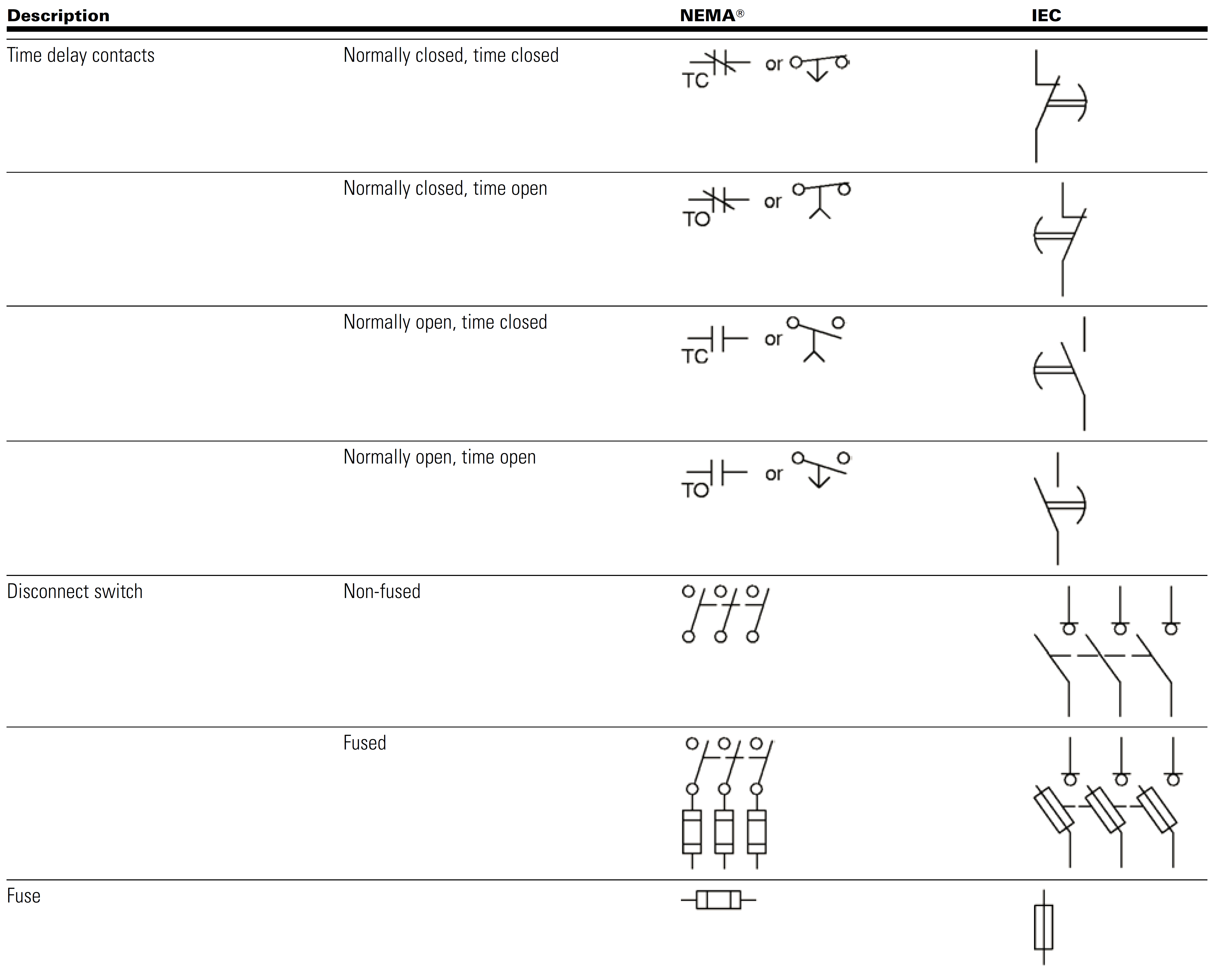
Electrical Schematic NEMA/IEC Electrical Symbols Comparison Page 2a
The International Electrotechnical Commission (IEC) has issued the second edition of Publication 204-1, Electrical Equipment for Industrial Machines. The National Fire Protection Association (NFPA) Committee 79 recently completed its work on the 1984 edition of the Electrical Standard for Industrial Machinery, covering metalworking machine tools, plastics machinery, and mass production.

Ansi Standard Electrical Schematic Symbols Wiring Draw
Units & Symbols for Electrical & Electronic Engineering The IET 2016 (The Institution of Engineering and Technology is registered as a Charity in England & Wales (no 211014) and Scotland (no SC038698). 4 3. Unit Symbols Unit symbols are printed in upright roman characters and are used after numerical values (e.g. 10 A, but 'a few amperes').

How to Read and Interpret Electrical Shop Drawings Part Three
Because of both the increasing opportunity and the need for medium voltage electrical power distribution in petrochemical facilities, there is an opportunity to adopt MV switchgear or controlgear design based on ANSI or IEC standards, according to each plant's specifications.
How to Read and Interpret Electrical Shop Drawings Part Three
4 min read Adhering to the right PCB standards is imperative when quality and safety are of utmost importance. However, it is often a challenge for companies trying to mark global footprints to bridge the gap between different standards. When it comes to the US, comparing ANSI vs IEC standards is a common debate amongst designers.

How to Read and Interpret Electrical Shop Drawings Part Three
AutoCAD Electrical Symbols - ANSI & IEC Spec Electrical Blocks IEC / ASNI 1450 Electrical Library Blocks and Symbols all comply with the ANSI Y32.2 or the IEC 617 standards. Recently updated! See more on how to draw electrical circuits video (below). How to draw an electrical circuit in AutoCAD Electrical Symbol Library
Ansi Vs Iec Electrical Symbols ubicaciondepersonas.cdmx.gob.mx
Relay symbols and device numbers; selection from IEC 617-, IEEE C37.2-1991 and IEEE C37.2-1979 1MRK 590 006-BEN Page 3 Test switch contacts 1. Break-contact (voltage supply circuit), late opening and early closing upon insertion and withdrawal, respectively, of the test han-dle. Note that the test switch contacts number 1 and 18 (12) will not.
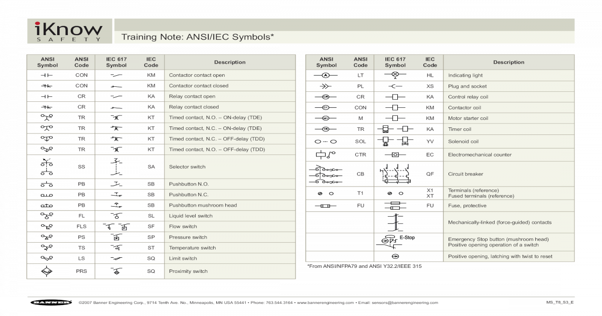
VISION iKnow Training Note ANSI/IEC Symbols*info. SQ Proximity switch
1. ANSI is a design-based standard, while IEC tends to be a performance-based standard. a. ANSI standards can specify sheet metal thickness, paint color, barriers and other features to ensure consistency of equipment from various manufacturers. This means that most manufacturers' equipment designed to the same standard vary little from one another.
Iec Vs Ansi Electrical Symbols Practical Troubleshooting Of
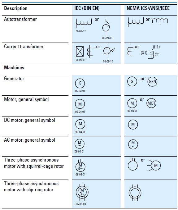
IEEE C37.2 IEC 60617 Comparison Of Electrical Circuit Symbols of IEC Vs. ANSI / IEEE The important practice in using graphical symbols is not mixing electrical symbols from different standards in one drawing.
industrial electrical schematic symbols
ANSI/IEC Relay Symbols 84,448 views There are two methods for indicating protection relay functions in common use.
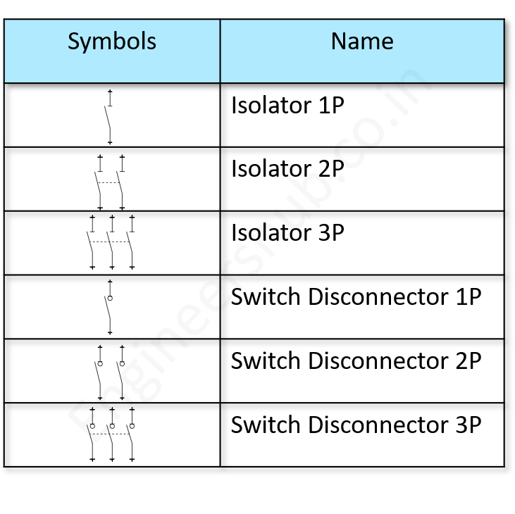
100+ Essential Electrical Symbols As Per IEC Standard Engineers Hub
The ANSI is an American organization that is responsible for establishing technical standards and norms in various sectors, including electronics and electricity. It was founded in 1918 and aims to promote competitiveness and innovation in the industry. ANSI also develops standards for electrical symbology. In electrical symbology, ANSI uses a.
Electrical Schematic NEMA/IEC Electrical Symbols Comparison Page 1b
The ANSI / IEC standards symbols are fully compatible with AutoCAD and AutoCAD LT. This Symbol Library containing over 1450 symbols! Uses ANSI / IEC Standards Access Block Library from menu Works with both AutoCAD and LT
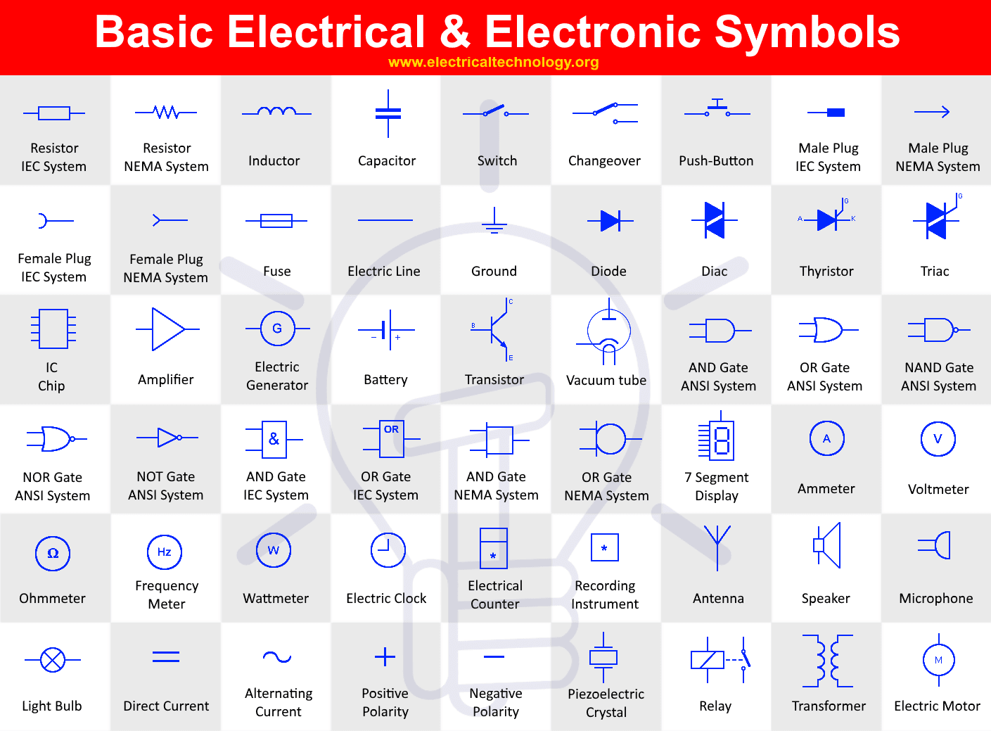
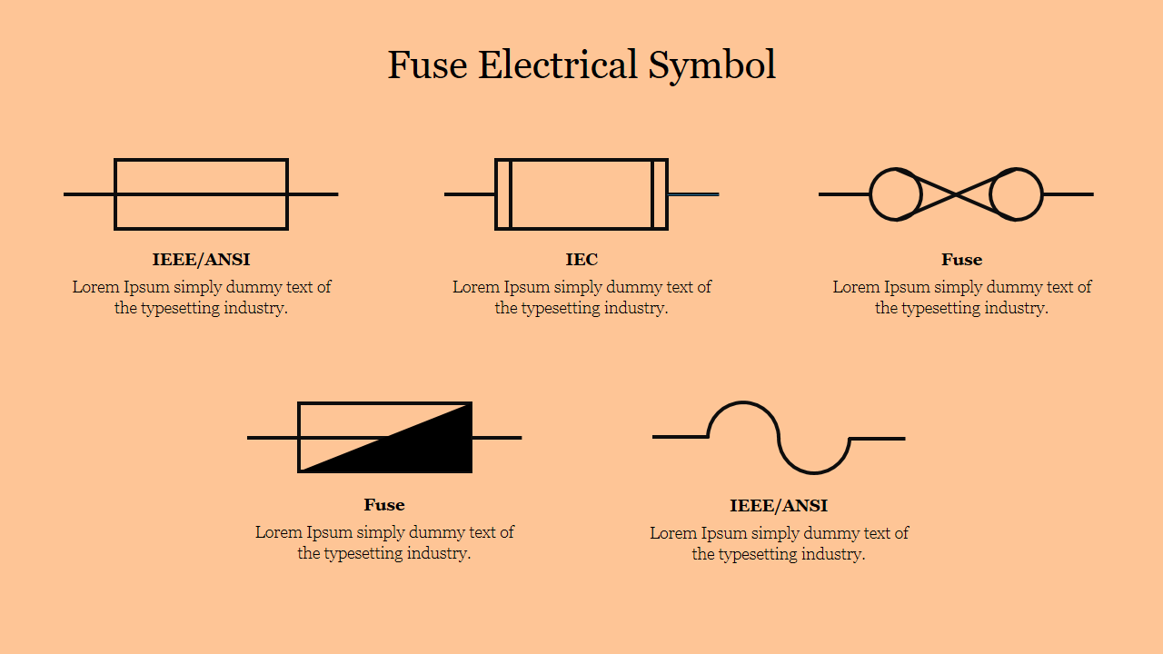
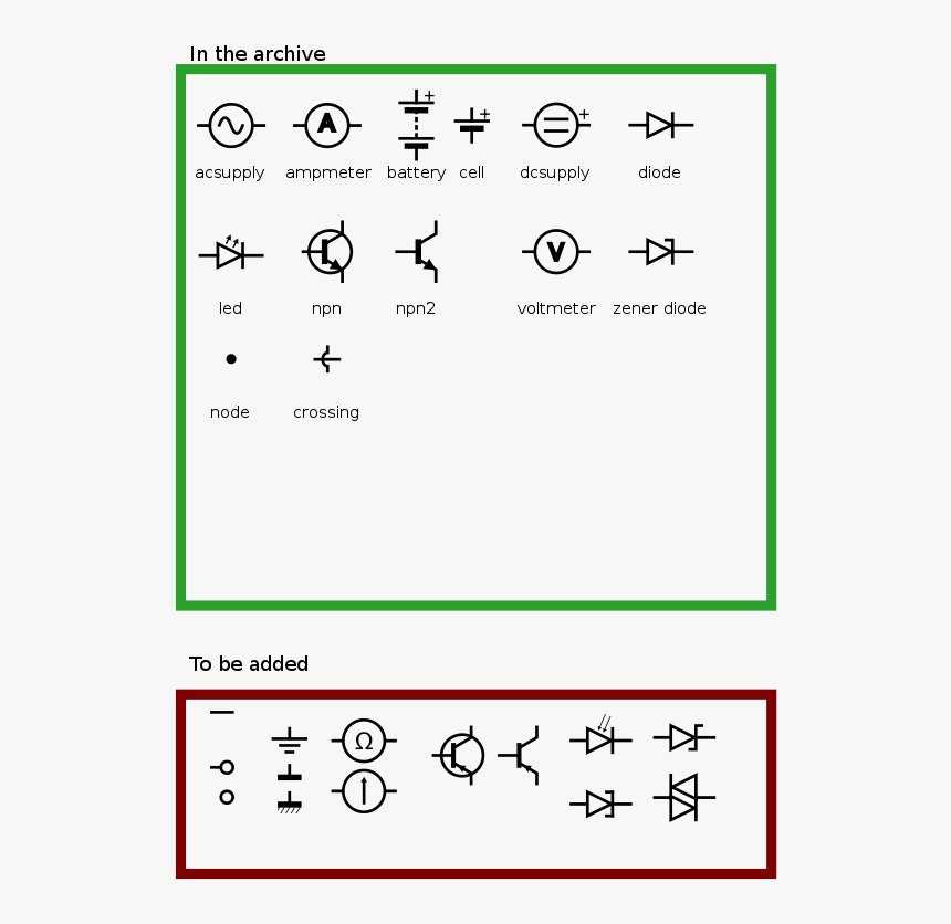
Basic & Important Electrical Symbols and Electronic Symbols
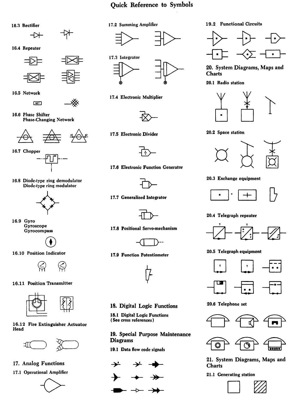
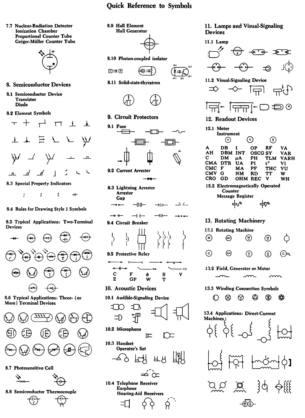
Common circuit diagram symbols (US ANSI symbols). An electronic symbol is a pictogram used to represent various electrical and electronic devices or functions, such as wires, batteries, resistors, and transistors, in a schematic diagram of an electrical or electronic circuit.These symbols are largely standardized internationally today, but may vary from country to country, or engineering.

Simbologia Ansi, Iec, Din PDF
Training Note: ANSI/IEC Symbols* ANSI Symbol ANSI Code IEC 617 Symbol IEC Code Description CON KM Contactor contact open CON KM Contactor contact closed CR KA Relay contact open CR KA Relay contact closed TR KT Timed contact, N.O. - ON-delay (TDE) TR KT Timed contact, N.C. - ON-delay (TDE) TR KT Timed contact, N.C. - OFF-delay (TDD)